 KAM Selectable Electric
Locker KAM Selectable Electric
LockerPart 1 - Installation with Bill Johnston
The first unit destined for the US (of the new design) was delivered to us to install and test. We will be reporting its performance on the kinds of trails not seen in the UK. Yes folks, it is destined to hit the rocks of Las Cruces and the surrounding areas to test its capabilities. But first we have to install it. This month we go through the installation of the locker components into the differential and the modifications that must be done to the axle housing. The locker is installed in four steps. First we have to prepare the housing, the new axle shafts, the differential and then finish up with final assembly and testing. The Axle Housing |
||
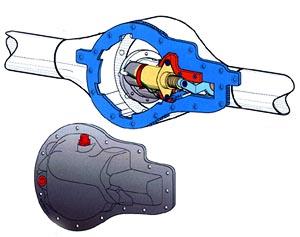
  Ok,
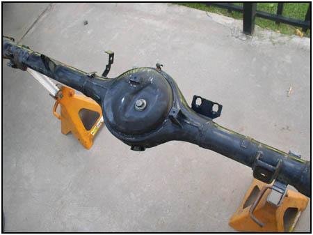
first question: If we are adding a locker, why are we looking at the rear of
an axle housing? The pieces that make it an electric locker have to go
somewhere, and with the the housing built only to house the gears - it has
to grow (and be easy to access). Ok,
first question: If we are adding a locker, why are we looking at the rear of
an axle housing? The pieces that make it an electric locker have to go
somewhere, and with the the housing built only to house the gears - it has
to grow (and be easy to access).
*Important Note* |
||
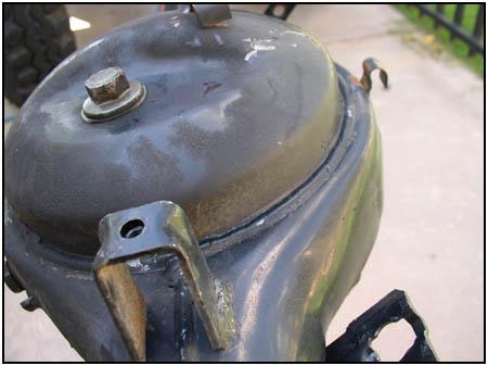
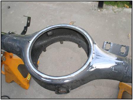
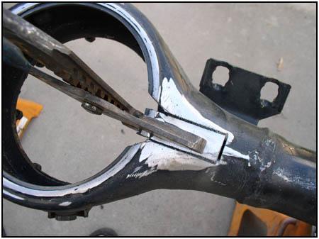
  We
start by removing the rear 'dish'. This is easily done with a cutoff wheel
or a reciprocating saw. We used both. The cutoff wheel made the initial cuts
and the 'sawz-all' did the rest. Be sure to cut just above the factory weld. This
assures that you don't go too deep and that you have something to work with
when making sure the finished cut is flat. We
start by removing the rear 'dish'. This is easily done with a cutoff wheel
or a reciprocating saw. We used both. The cutoff wheel made the initial cuts
and the 'sawz-all' did the rest. Be sure to cut just above the factory weld. This
assures that you don't go too deep and that you have something to work with
when making sure the finished cut is flat. |
||
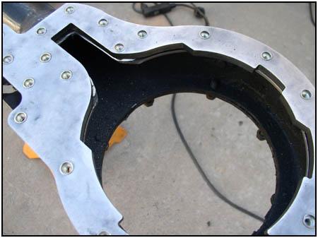
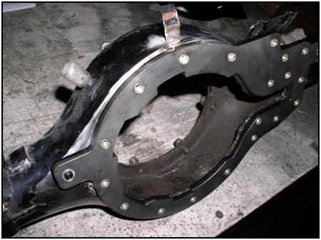
 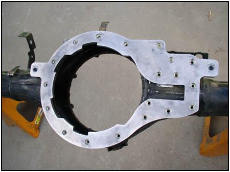 This
should leave a weld height of about 2mm. Using the new mounting ring as a
flat surface to gauge off of, make sure that it fits flush and even. The
larger diameter cuts should line up fit perfectly with the inner edge of the
housing. This
should leave a weld height of about 2mm. Using the new mounting ring as a
flat surface to gauge off of, make sure that it fits flush and even. The
larger diameter cuts should line up fit perfectly with the inner edge of the
housing. |
||
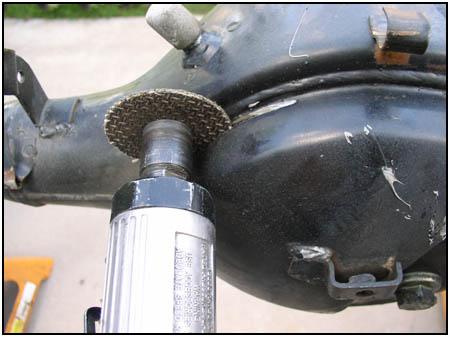
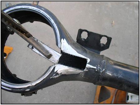
 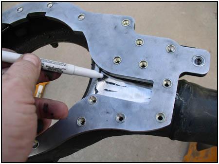 Cleaning
up the long side tube where the bracket will sit will give you a clean
surface to mark for the cuts in the
material that will have to be removed. This section will be strengthened by
the new bracket, so no worries there. Cleaning
up the long side tube where the bracket will sit will give you a clean
surface to mark for the cuts in the
material that will have to be removed. This section will be strengthened by
the new bracket, so no worries there. |
||
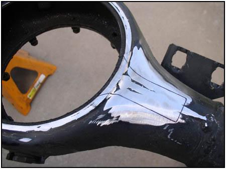  Again,
using a cutoff wheel or reciprocating saw, cut out the section marked above.
Clean up the sharp edges. Again,
using a cutoff wheel or reciprocating saw, cut out the section marked above.
Clean up the sharp edges. |
||
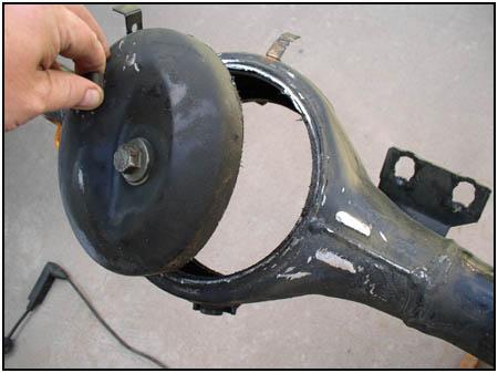
  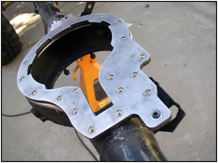 When
finished, again use the mounting ring to check to see that the openings
match. When
finished, again use the mounting ring to check to see that the openings
match. |
||
  The
instructions (which were unusually clear and concise) gave us the option to
apply the supplied Loctite 598 gasket material before OR after welding. We
did it before we tacked the mounting ring in place. The
instructions (which were unusually clear and concise) gave us the option to
apply the supplied Loctite 598 gasket material before OR after welding. We
did it before we tacked the mounting ring in place. |
||
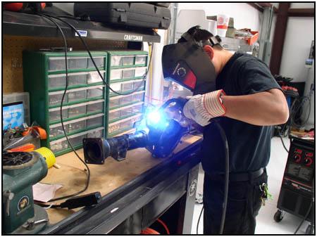 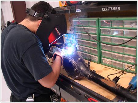 Taking
it to a friends shop, we MIG welded the ring into place. Be sure not to do one
continuous weld, as the heat can bend the housing and make it unusable. If
you are new to welding, take it to a shop that can be trusted. Taking
it to a friends shop, we MIG welded the ring into place. Be sure not to do one
continuous weld, as the heat can bend the housing and make it unusable. If
you are new to welding, take it to a shop that can be trusted.
KAM is also working on a 'glue' that will allow you to attach the ring without welding. You would then need a grinder to remove the ring if the placement is off... This is the same material that they use to attach railway cars to their chassis, so it sounds pretty strong! |
||
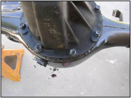
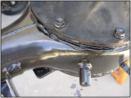
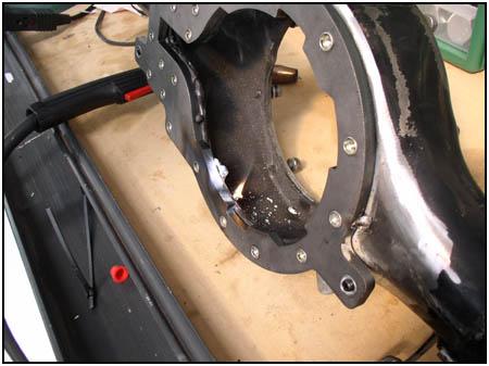  Here
we can see where the welding heated up the Loctite a little to much. No
worries because the fumes are non-toxic, just put it out and move on. Here
we can see where the welding heated up the Loctite a little to much. No
worries because the fumes are non-toxic, just put it out and move on.
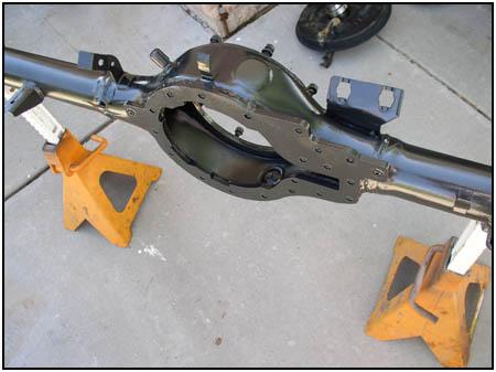
The finished weld should make a leak-proof seal all around the ring. This is very important if you want to retain oil and not make a puddle in the driveway... To the right you can see the finished housing, painted and ready. The Axle Shafts |
||
|
|
||
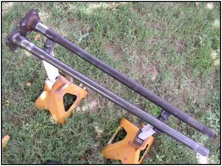
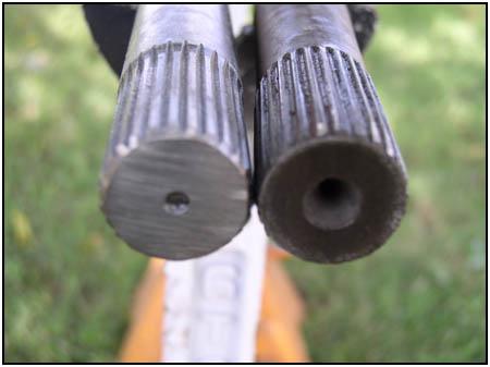
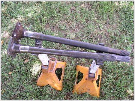
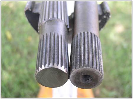
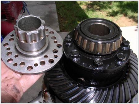
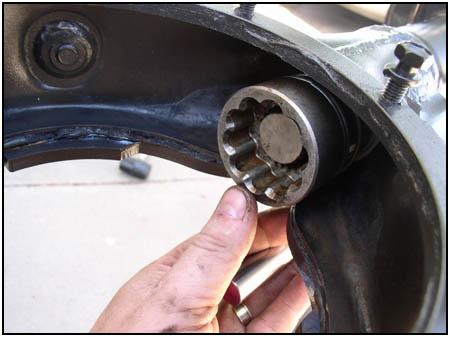
| The KAM locker comes with a new set of axle shafts. These have been tested to be 40% stronger than stock axle shafts. You can also see the thicker, splined section in the short shaft that is a key part of the mechanism. | ||
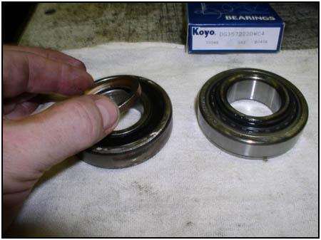  Bearings,
retainers and seals are also included in the kit. But one thing you will
notice right away is that the bearings look a little different. While Suzuki
stopped importing the Samurai style vehicle to the US, the rest of the world
has seen improvements in the components. The new bearing incorporates the
spacer into its design. In the photo on the left you can see the bearings
(old style on the left with the spacer, new style on the right). Bearings,
retainers and seals are also included in the kit. But one thing you will
notice right away is that the bearings look a little different. While Suzuki
stopped importing the Samurai style vehicle to the US, the rest of the world
has seen improvements in the components. The new bearing incorporates the
spacer into its design. In the photo on the left you can see the bearings
(old style on the left with the spacer, new style on the right).
The Differential |
||
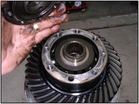
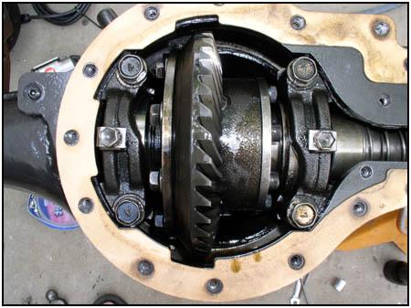
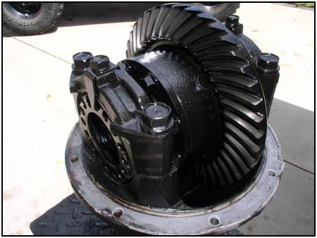  In
the differential, we have to replace the end cap on the carrier with a new
locking flange. So the first thing will be to remove the carrier from the
differential. In
the differential, we have to replace the end cap on the carrier with a new
locking flange. So the first thing will be to remove the carrier from the
differential. |
||
 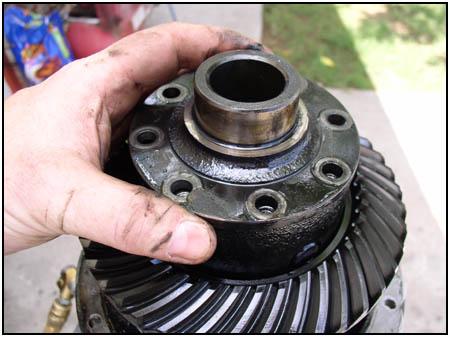 Here
you can see the new flange next to the end that we are going to be working
with. If you have new bearings you want to install, now is the time to do
it. Removing the 8 stock bolts is all it takes to remove the cap. Here
you can see the new flange next to the end that we are going to be working
with. If you have new bearings you want to install, now is the time to do
it. Removing the 8 stock bolts is all it takes to remove the cap. |
||
  There
may be thrust washers under the end cap, if so, make sure you put them back
into the carrier. The flange is a direct replacement for the end cap. There
may be thrust washers under the end cap, if so, make sure you put them back
into the carrier. The flange is a direct replacement for the end cap. |
||
  Torque
the new socket head cap screws to factory specs and install the bearing.
Loctite is also included to keep the screws from doing something stupid
later on. The carrier is then installed back into the differential. You will
need to set up the ring and pinion with the correct backlash, so don't just
bolt it together and call it 'good'. Torque
the new socket head cap screws to factory specs and install the bearing.
Loctite is also included to keep the screws from doing something stupid
later on. The carrier is then installed back into the differential. You will
need to set up the ring and pinion with the correct backlash, so don't just
bolt it together and call it 'good'. |
||
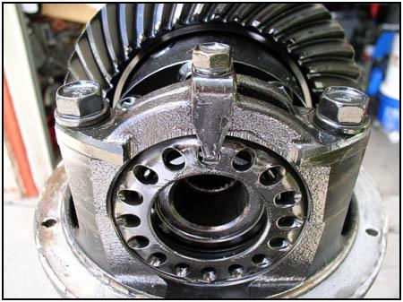
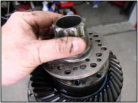
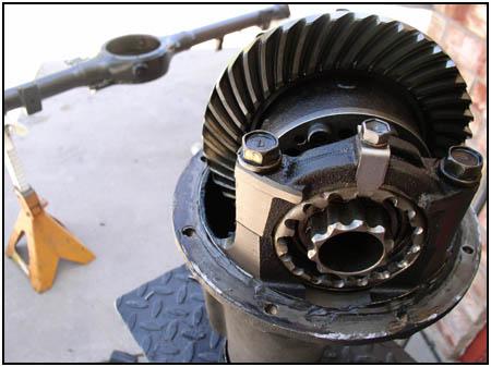
  You
will be using a new (replacement) bearing adjuster. Look closely at the
photo on the left and you will see that the inside diameter of the bearing
adjuster ring has been clearanced to allow the sliding dog to fit into the
carrier, over the new locking flange. When locked into place, this will lock
the carrier to the splined short axle shaft to essentially turn the carrier
into a spool. The fact that it is engaged only when you need it (turning it
on) makes it a selectable locker. You
will be using a new (replacement) bearing adjuster. Look closely at the
photo on the left and you will see that the inside diameter of the bearing
adjuster ring has been clearanced to allow the sliding dog to fit into the
carrier, over the new locking flange. When locked into place, this will lock
the carrier to the splined short axle shaft to essentially turn the carrier
into a spool. The fact that it is engaged only when you need it (turning it
on) makes it a selectable locker. |
||
| Final Assembly | ||
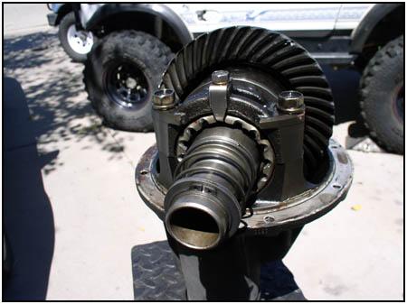
  Next
we put it all together. We used the same Loctite 598 gasket sealer to assure
a leak-proof connection between the diff and the housing. You can see on the
right where we have positioned the short axle shaft into the tube far enough
to rest the sliding dog in place. What you don't see underneath is the
actuator fork that slides over the dog before it is installed. You will see
it again when we flip over the housing. Next
we put it all together. We used the same Loctite 598 gasket sealer to assure
a leak-proof connection between the diff and the housing. You can see on the
right where we have positioned the short axle shaft into the tube far enough
to rest the sliding dog in place. What you don't see underneath is the
actuator fork that slides over the dog before it is installed. You will see
it again when we flip over the housing. |
||
  Just
make sure the sliding dog and axle shaft are out of the way before sliding
the differential into place. The differential has to be seated and torqued
down before continueing. Just
make sure the sliding dog and axle shaft are out of the way before sliding
the differential into place. The differential has to be seated and torqued
down before continueing. |
||
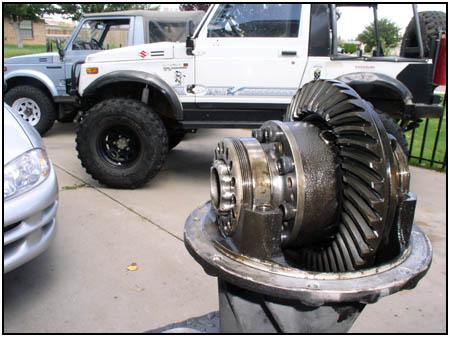
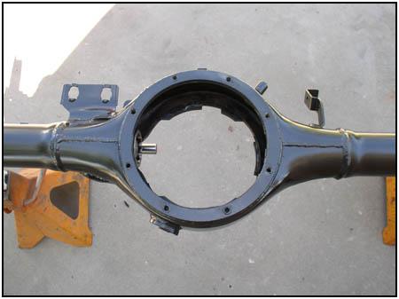
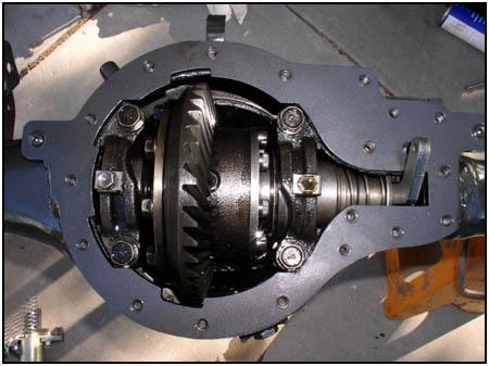
  When
you turn over the housing, check to see that the differential fits into the
ring like a key. Now, don't all those cutouts make sense? Once the position
has been triple checked, wipe the excess sealant off the differential
connection surface. When
you turn over the housing, check to see that the differential fits into the
ring like a key. Now, don't all those cutouts make sense? Once the position
has been triple checked, wipe the excess sealant off the differential
connection surface. |
||
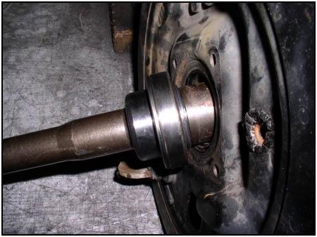
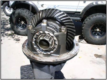
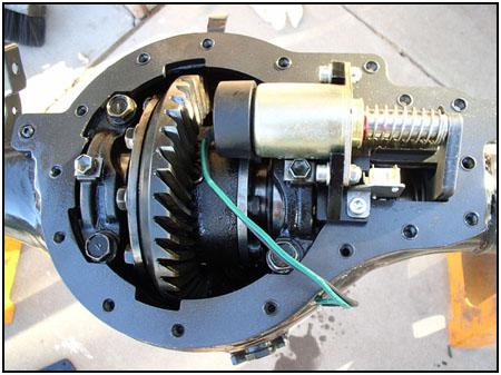
 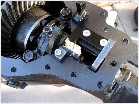 After
seating the axle shafts in place, you get to see how it all works. Here you
can see the actuator fork and how it moves the sliding dog along the axle
shaft and seats into the locking flange. We now start to assemble the
solenoid bracket and the warning lamp micro switch. After
seating the axle shafts in place, you get to see how it all works. Here you
can see the actuator fork and how it moves the sliding dog along the axle
shaft and seats into the locking flange. We now start to assemble the
solenoid bracket and the warning lamp micro switch. |
||
 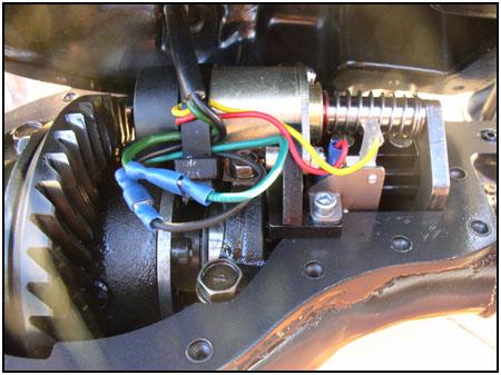 The
solenoid assembly gets bolted in next. The wiring threads through the new
diff cover and gets hooked up according to the instructions. Nothing hard
there, just make sure the wires are tied down so they don't get chewed up in
the ring gear. This is where we hooked up the electrical to a battery to
test everything out. The locker is designed to engage in 0.8 of a second. The
solenoid assembly gets bolted in next. The wiring threads through the new
diff cover and gets hooked up according to the instructions. Nothing hard
there, just make sure the wires are tied down so they don't get chewed up in
the ring gear. This is where we hooked up the electrical to a battery to
test everything out. The locker is designed to engage in 0.8 of a second. |
||
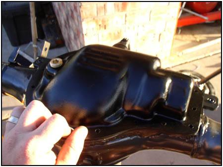 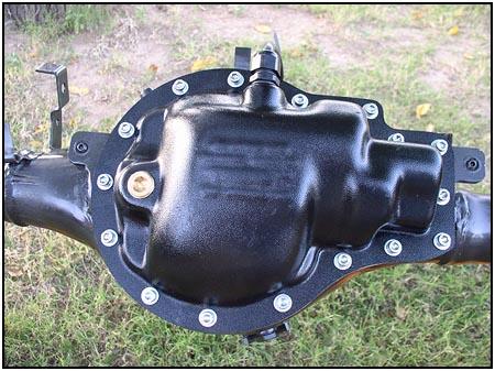 The
paper gasket is set into place under the cover and bolted down using the 16
stainless steel socket head cap screws provided. The new oil filler plug is
now on the left. The
paper gasket is set into place under the cover and bolted down using the 16
stainless steel socket head cap screws provided. The new oil filler plug is
now on the left.
KAM is also looking at releasing a Heavy Duty Alloy Diff Pan / Diff Guard and a Heavy Duty Rock Slider / Diff Guard. Come back next month to see us bolt it to a Samurai and hit the rocks! |
||
| Kam Differentials isn't just a name, they DO specialize in differentials. They are working on a Limited Slip Differential (LSD) for the Samurai. The new LSD will be fully compatible with the electric locker, so you can install either - or both! It is currently under development and should be released in 4-6 months. | ||
|
Manufacturer:
KAM Differentials
LTD. US Supplier:
Low Range
Off-Road, LC |
08/22/2022
 A few years back, when I first looked into the different lockers that
were available for a
Samurai, I came across a company that built one designed to be either
cable or air actuated. I never got a chance to see one in person, but it
sounded interesting. Well, that same company, KAM Differentials Ltd.,
has redesigned their locker and made it electric! There is no longer a
requirement for an on board air system or a mechanical cable system -
just a switch in the dash.
A few years back, when I first looked into the different lockers that
were available for a
Samurai, I came across a company that built one designed to be either
cable or air actuated. I never got a chance to see one in person, but it
sounded interesting. Well, that same company, KAM Differentials Ltd.,
has redesigned their locker and made it electric! There is no longer a
requirement for an on board air system or a mechanical cable system -
just a switch in the dash.