|
|
ARB
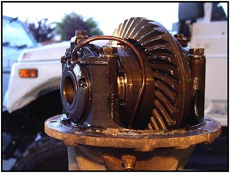
'Rear to Front' Conversion So you decided to upgrade the rear axle to one of the new 'hybrid' models that are getting popular like our Spidertrax Sidewinder... The only problem is, you spent part of last seasons budget on a new ARB Air Locker for the rear, and now you can't use it in the new (larger) carrier! NO PROBLEM! With a little elbow grease and the right component parts you can convert that rear Air Locker into a front Air Locker. |
|
  The
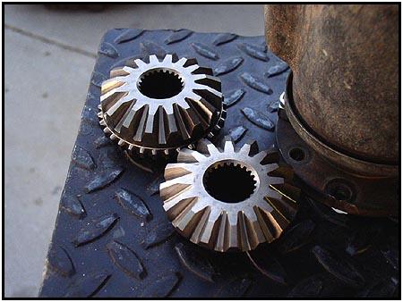
rear axle shafts in a Samurai have 26 splines and the front shafts have 22
splines. The components that make the real difference in swapping the
carrier are the side gears.
The folks at Air Locker Inc. (ARB - here in the USA) supplied us with a
set of 22 spline side gears to make the conversion. Here is how... The
rear axle shafts in a Samurai have 26 splines and the front shafts have 22
splines. The components that make the real difference in swapping the
carrier are the side gears.
The folks at Air Locker Inc. (ARB - here in the USA) supplied us with a
set of 22 spline side gears to make the conversion. Here is how... |
||
 To
do this we have to pull the carrier from the differential housing. We
started by disconnecting the air line from the bulkhead body (differential
housing fitting). Be very careful not to kink the copper air line tubing
as it is the 'life line' for the Air Locker. To
do this we have to pull the carrier from the differential housing. We
started by disconnecting the air line from the bulkhead body (differential
housing fitting). Be very careful not to kink the copper air line tubing
as it is the 'life line' for the Air Locker. |
||
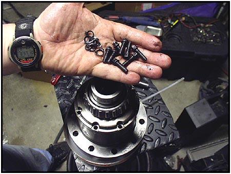
  Next
we cleaned off the seal housing so that we could locate and remove the
three cap screws that hold the seal housing in place. You will need to
pull out your allen wrenches for this step. Be careful not to drop these
cap screws into the housing, as you can really do some damage if they get
caught up in the pinion bearings down below. Next
we cleaned off the seal housing so that we could locate and remove the
three cap screws that hold the seal housing in place. You will need to
pull out your allen wrenches for this step. Be careful not to drop these
cap screws into the housing, as you can really do some damage if they get
caught up in the pinion bearings down below. |
||
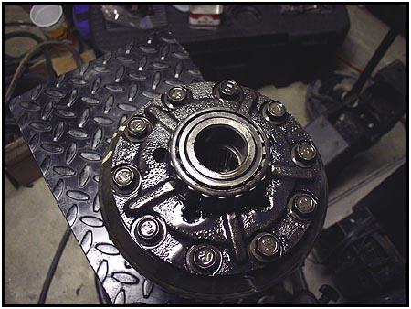
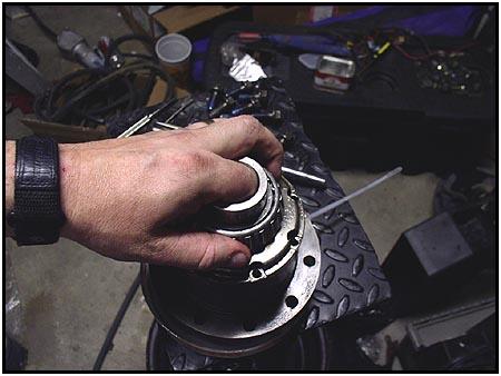
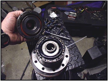
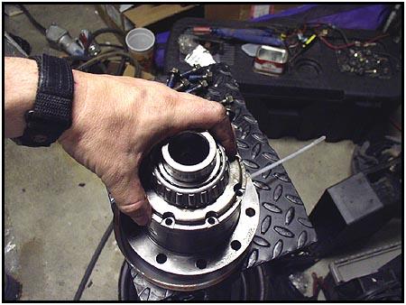
  We
gently pulled the seal housing off of the bearing journal. Check the
rubber o-rings in the seal housing for wear and tear. Any cracks, tears or
flat spots can cause an air leak and this will render you air locker
inoperable. We
gently pulled the seal housing off of the bearing journal. Check the
rubber o-rings in the seal housing for wear and tear. Any cracks, tears or
flat spots can cause an air leak and this will render you air locker
inoperable. |
||
|
||
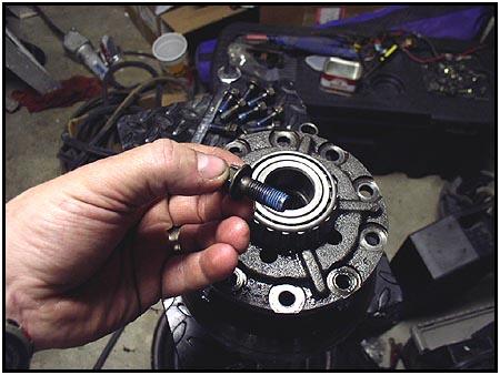
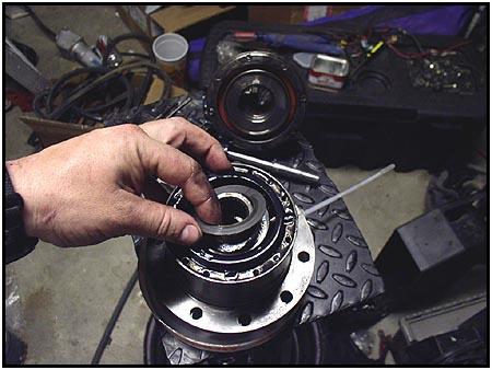
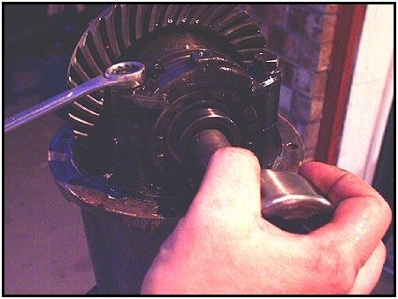  Removing
the bearing adjuster stopper and bearing cap bolts can be tricky if you
have everything mounted to the table using the pinion flange as we do, so
we use a spare (grenaded) birfield to hold everything still. They are also
26 spline, so they slide right into a rear side gear. Removing
the bearing adjuster stopper and bearing cap bolts can be tricky if you
have everything mounted to the table using the pinion flange as we do, so
we use a spare (grenaded) birfield to hold everything still. They are also
26 spline, so they slide right into a rear side gear. |
||
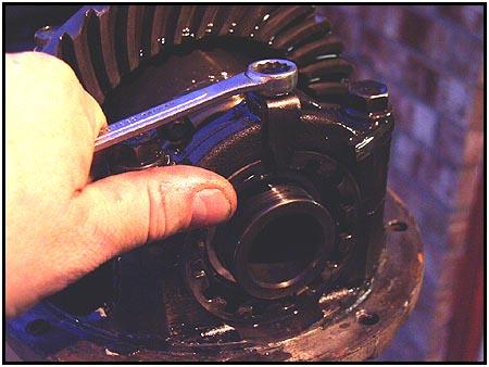
  Once
the bearing cap and adjuster ring has been removed it is just a matter of
laying the parts out on the table to keep them straight. Once
the bearing cap and adjuster ring has been removed it is just a matter of
laying the parts out on the table to keep them straight. |
||
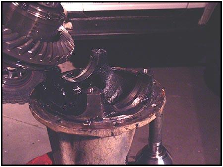  The
carrier can then be lifted away from the differential housing. This is the
time where you can clean up the bulkhead fitting if any foreign matter has
found its way into it. We then set the differential housing aside to concentrate
on the carrier itself. The
carrier can then be lifted away from the differential housing. This is the
time where you can clean up the bulkhead fitting if any foreign matter has
found its way into it. We then set the differential housing aside to concentrate
on the carrier itself. |
||
 We
then turned the carrier so that the 10 ring bolts were facing up. To
remove the bolts, it is easier to use an air impact gun. We
then turned the carrier so that the 10 ring bolts were facing up. To
remove the bolts, it is easier to use an air impact gun. |
||
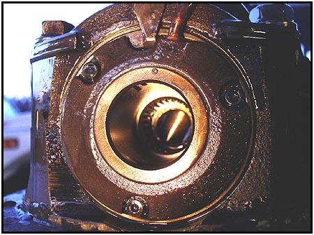
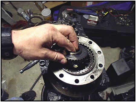
  Suzuki
hasn't let us down. They use their version of locktite here to make sure
nothing comes loose and screws up your day halfway through the
trail... but to do upgrades or repairs, it can get tedious.
Splitting the carrier (lifting the housing cover) allowed us to see one of
the side gears. Suzuki
hasn't let us down. They use their version of locktite here to make sure
nothing comes loose and screws up your day halfway through the
trail... but to do upgrades or repairs, it can get tedious.
Splitting the carrier (lifting the housing cover) allowed us to see one of
the side gears. |
||
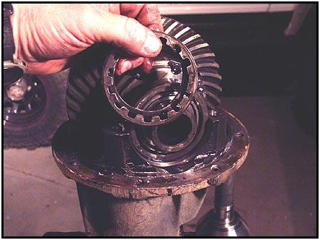
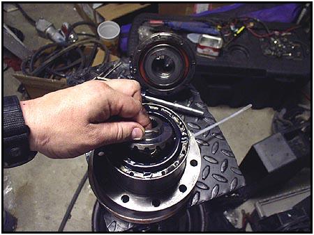
 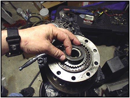 Don't
lose the thrust washer as it is very important! Remove the side gear by
simply lifting it out. Don't
lose the thrust washer as it is very important! Remove the side gear by
simply lifting it out. |
||
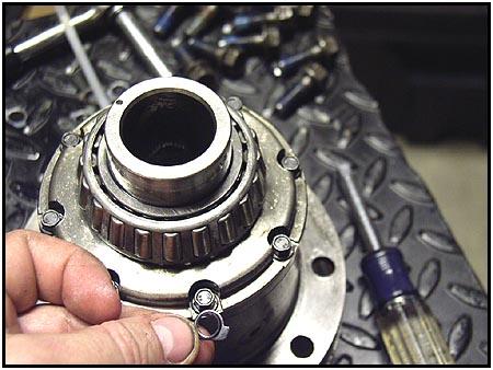
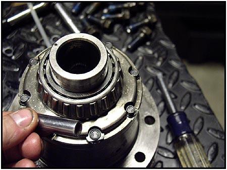
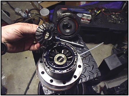
 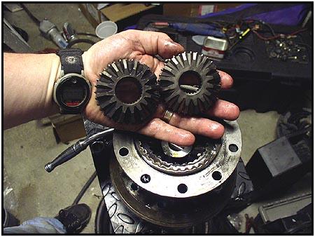 Holding
the two sizes of side gears side by side shows the difference in the axle
shaft opening. Set the new sidegear in place. Assembling is just the reverse of what we just did. Holding
the two sizes of side gears side by side shows the difference in the axle
shaft opening. Set the new sidegear in place. Assembling is just the reverse of what we just did. |
||
  Don't
forget that thrust washer! Don't
forget that thrust washer!
Putting the carrier back together is easy, keeping it together as you do the other side is not. We just used a zip tie through one of the bolt holes and it worked fine. You could also reinstall the ring gear, but since we were only half done (and we didn't want to make a mistake and damage the ring gear) we will stick with the zip tie for now. |
||
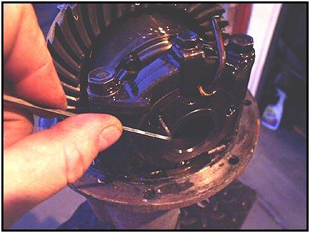
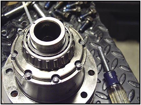
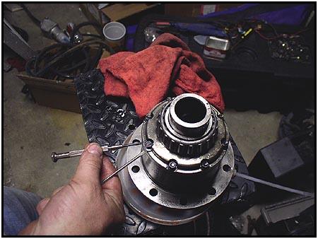  Flipping
the carrier over, we get to the more complicated part. This side is held
together with a series of stretch bolts that are held in place with
pressed on retainers. These retainers can be removed using a small flat
tip screw driver pushed under the edge of the retainer to work it off.
Then the bolts can be removed. Flipping
the carrier over, we get to the more complicated part. This side is held
together with a series of stretch bolts that are held in place with
pressed on retainers. These retainers can be removed using a small flat
tip screw driver pushed under the edge of the retainer to work it off.
Then the bolts can be removed. |
||
 After
you finish removing the bolts and retainers... throw them away.
These have to be replaced with new components when you reassemble the
carrier. Why? Because you don't re-use stretch bolts or their retainers.
You can get the new bolts and retainers when you order your new side
gears. After
you finish removing the bolts and retainers... throw them away.
These have to be replaced with new components when you reassemble the
carrier. Why? Because you don't re-use stretch bolts or their retainers.
You can get the new bolts and retainers when you order your new side
gears. |
||
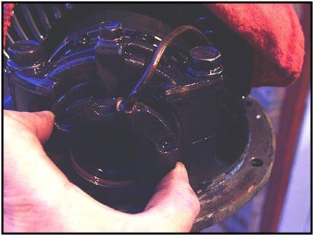
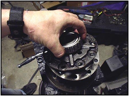
  Lift
the top and be careful not to get anything in the rubber seal you can see
in the cap. Although it looks a little different, all the parts you need
to get to are in the same place as it was on the other side. Lift
the top and be careful not to get anything in the rubber seal you can see
in the cap. Although it looks a little different, all the parts you need
to get to are in the same place as it was on the other side. |
||
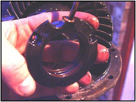
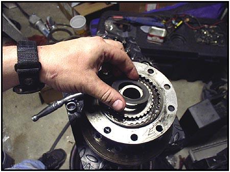
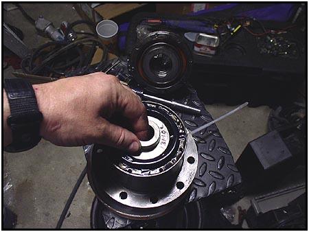
  Remember
the thrust washer again, and lift out the side gear. Remember
the thrust washer again, and lift out the side gear. |
||
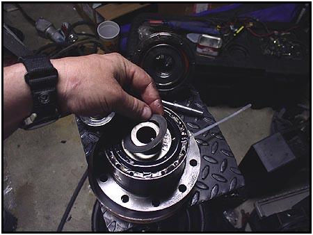
 Replace
this side gear as you did on the other side. Replace
this side gear as you did on the other side.
*NOTE* |
||
  Gently
drop in the side gear and then the thrust washer. Gently
drop in the side gear and then the thrust washer. |
||
  Check
the cap for anything that may have made its way in there and replace the
cap. Check
the cap for anything that may have made its way in there and replace the
cap. |
||
|
Check
the cap for anything that may have made its way in there and replace the
cap. |
||
 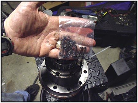 Here
we see the NEW STRETCH BOLTS AND RETAINERS that we talked about earlier.
They come from ARB with a locktite compound already applied (photo on the
right) Here
we see the NEW STRETCH BOLTS AND RETAINERS that we talked about earlier.
They come from ARB with a locktite compound already applied (photo on the
right) |
||
| The action in this sequence is all at the bottom of the photo. Click through the picture for a closer look. Once the bolts are all torqued down, the retainers are pressed into place with a few taps of a hammer using a small socket to seat it. | ||
|
|
||
 And
that is basically it. Reassemble in the reverse order and make sure you
take your time to do it right. Rebuilding it on the trail is a royal pain. And
that is basically it. Reassemble in the reverse order and make sure you
take your time to do it right. Rebuilding it on the trail is a royal pain.
But now you have an Air Locker for the front, and you are going to enjoy it! |
||
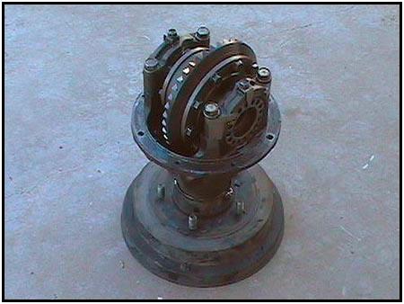 *You
may have noticed the stand that we used during this buildup. It was
specially constructed to do work on Suzuki differentials. It has a hole drilled out in
the center so that you can get to the pinion nut while the flange is
bolted to the stand. Both drive shaft
bolt patterns are drilled out of the center so that the either pattern drive shaft flange can
be bolted to the stand for stability. If you want to work on a Sammy diff on your workbench
without going to such an extent, you can use a rear brake drum in the same
manner. Balance the diff on the drum and use a bolt to hold it in place. *You
may have noticed the stand that we used during this buildup. It was
specially constructed to do work on Suzuki differentials. It has a hole drilled out in
the center so that you can get to the pinion nut while the flange is
bolted to the stand. Both drive shaft
bolt patterns are drilled out of the center so that the either pattern drive shaft flange can
be bolted to the stand for stability. If you want to work on a Sammy diff on your workbench
without going to such an extent, you can use a rear brake drum in the same
manner. Balance the diff on the drum and use a bolt to hold it in place. |
||
| Source:
ARB Corporation Limited |
03/14/2017