|
Rear Driveshaft Disconnect with Bill Johnston
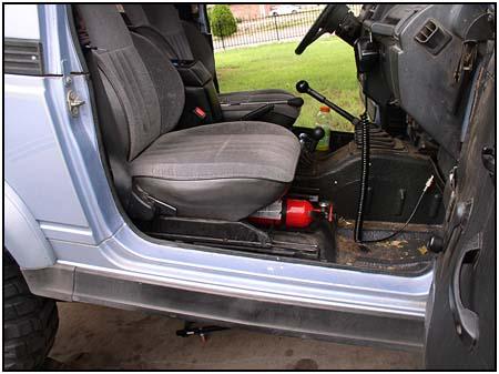
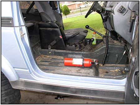
Before starting, you will need to raise the vehicle enough to work under it safely. You can do this with a set of car ramps under the rear tires. Make sure the emergency brake is on and the wheels are chocked. This component can be installed without removing the transfer case. |
||
|
|
||
|
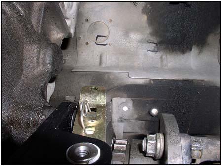
Transfer Case Bracket Installation
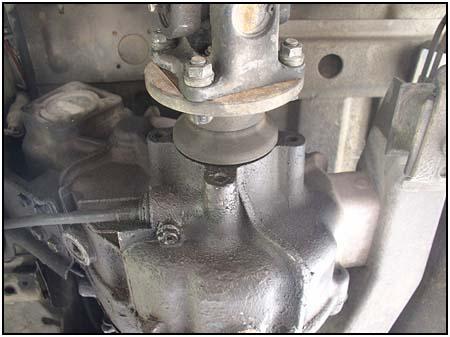
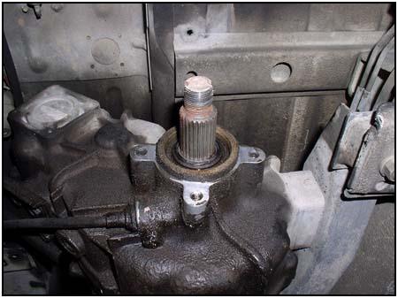
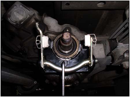
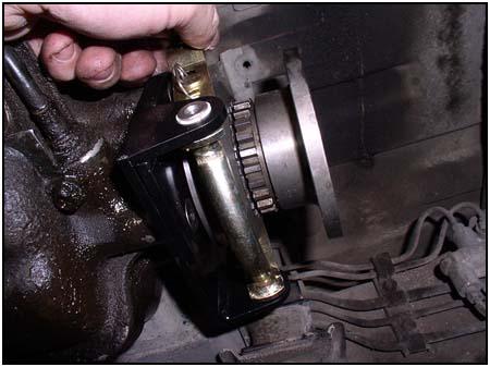
Remove the rear drive flange from the transfer case. |
||
|
|
||
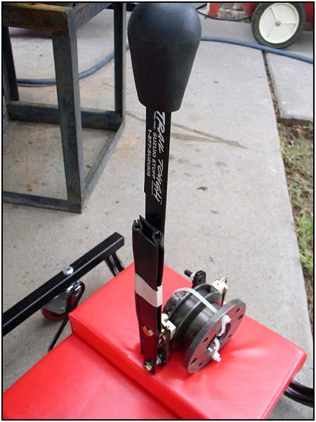
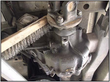
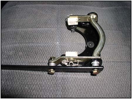
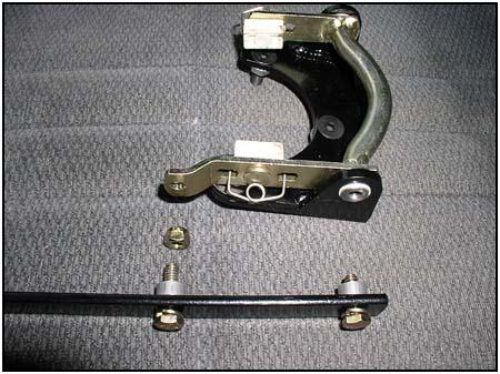
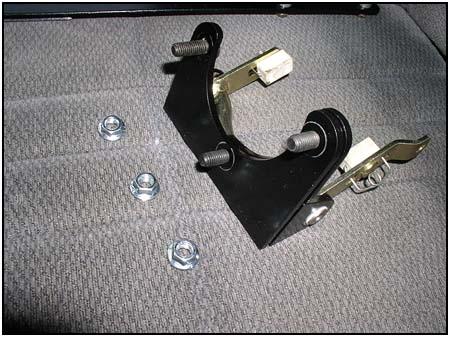
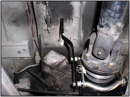
| Remove the shift handle from the carrier by removing the two retaining bolts and the three nuts from the allen head bolts and set them aside. Bolt the carrier into place on the transfer case using the recessed allen head bolts provided. | ||
|
|
||
|
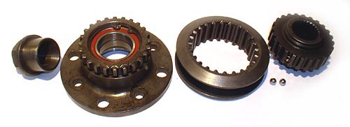
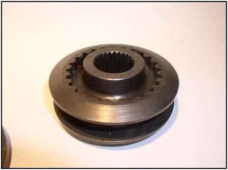
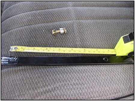
The Disconnect System is made up of 8 parts. From the left, they are the nut, the flange, the slide, two ball bearings and the hub. Not shown are the two springs that are inside the holes in the hub.
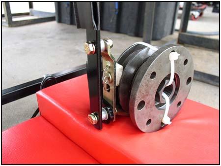
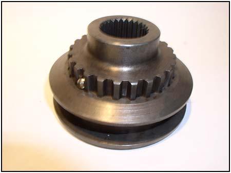
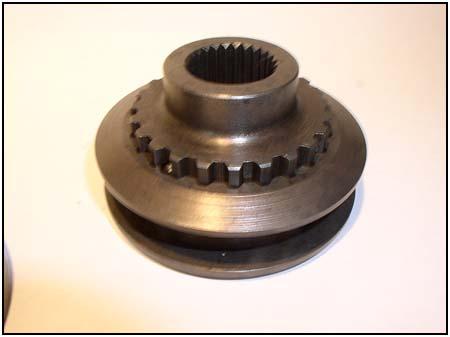
If you separate the hub and slide, make sure you don’t lose the two ball bearings or springs that allow the sections to slide easily. Make sure the ball bearings line up with the detents inside the slide. These allow the slider to rest in its proper position. They are critical.
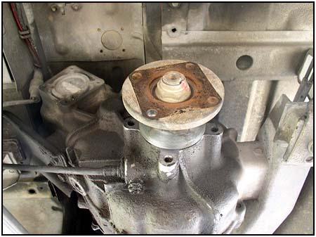
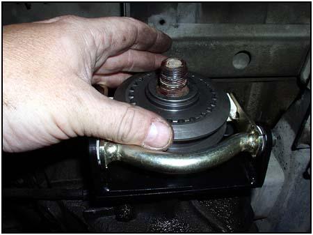
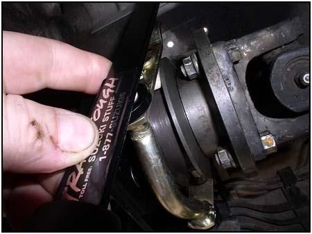
Slide the new flange into place on the rear drive output shaft, making sure to slide the white shoes into place as seen in the photo below.
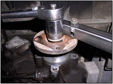
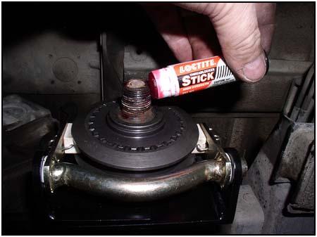
Using Red LocTite, install the new flange and retaining nut, being careful to slide the nut into the bearing without jamming it. Torque the retaining nut to 80-100 ft lbs (factory settings).
|
||
|
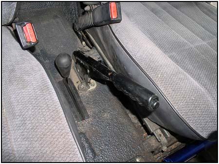
Shift Lever Installation
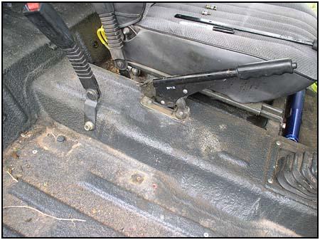
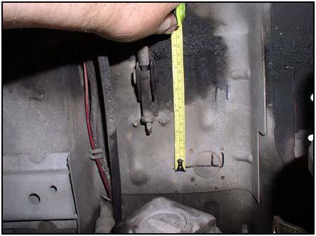
Make sure the slip ring is locked to the rear. Use the new shifter handle to point to the underside of the transmission tunnel, lining up the handle with the two mounting bolts.
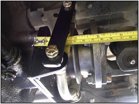
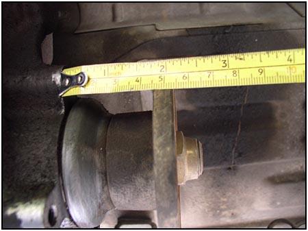
Mark this as the rear edge of the opening. Lock the slip ring to the front, line up the handle and mark the front edge of the opening. Measure the length of the opening and note the position relative to the emergency brake bolts that are seen from below. Remove the passenger seat, and any center console and/or accessories that are located on the transmission tunnel for ease of installation. If you have carpeting, remove it from the transmission tunnel.
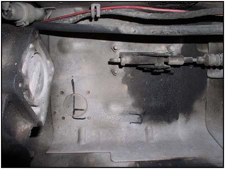
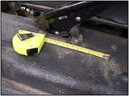
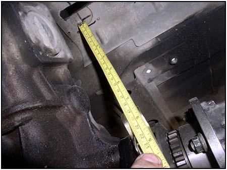
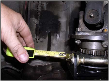
Find the location of the planned new opening relative to the emergency brake bolts as seen from inside the vehicle.
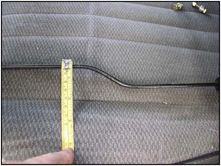
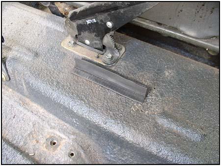
The left/right position of the slot can be adjusted to clear anything that may be in the way. These photos show the slot moved closer to the emergency brake. The slot needs to be ˝” wide. The rubber edges provided are 5” long and will allow just enough room for the handle to come through with minimal air gap. Measure three times, cut once… Adjust the handle for any left/right slot position change. Measure the distance the slot position was shifted and reform the handle accordingly.
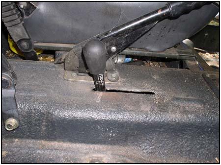
Remove the shifter grip and bolt the handle in place. Shift it forward and back to verify clearance for shifter handle. Shifter must fully engage the forward and rearward detent positions. Trim slot accordingly.
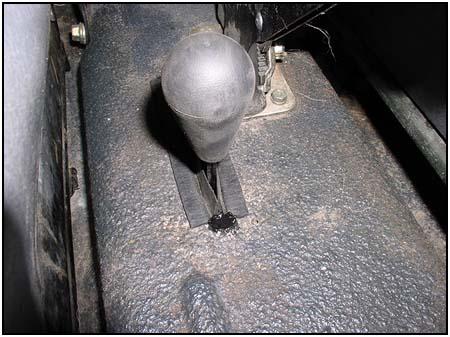
Remove handle and install rubber edges. Install the handle from below, gently sliding the handle through the rubber edges of the slot. Secure the handle with the bolts, lock washers and spacers provided. Install the shifter grip from inside the cab. Apply dab of Black RTV to ends of rubber where any air gap is seen.
Again, verify shifter operation by moving the handle from forward detent to rear detent. Reinstall the passenger seat and put away the tools, you’re done. |
||
| Source:
Trail
Tough Products |
08/22/2022