|
Spidertrax Anti-Wrap Kit with Bill Johnston
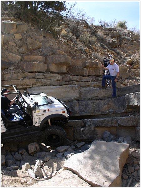
A traction bar can take the spring wrap out of the equation, but you have to choose the right one for your application. We installed a triangulated (looks like a triangle) traction bar in the past, and it worked very well. Too well in fact, as it transferred all of the drive train power directly to the wheels. In a trail rig, that worked amazingly well. But after driving the same rig on the street for a few months, the steady shock loads finally took their toll on the worn transfer case gears and killed the transfer case. What we needed was a traction aid that still left a little play in the drive train, kind of a 'buffer', so the gearing could work smoothly again. |
||
|
||
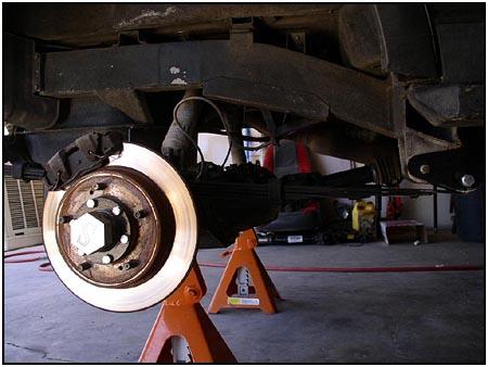
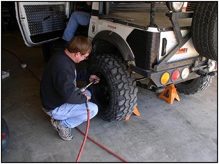  The
Spidertrax Anti-Wrap Kit can be installed with the vehicle flat on the
ground, but to make it a little easier for you to see how we did it, we
supported the rear axle on jack stands and removed the tires. The
suspension stayed right where it would normally be if it was still resting
on its tires. The
Spidertrax Anti-Wrap Kit can be installed with the vehicle flat on the
ground, but to make it a little easier for you to see how we did it, we
supported the rear axle on jack stands and removed the tires. The
suspension stayed right where it would normally be if it was still resting
on its tires. |
||
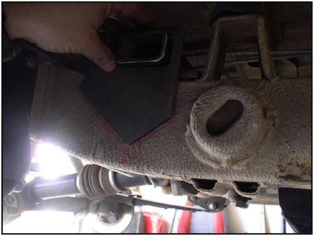
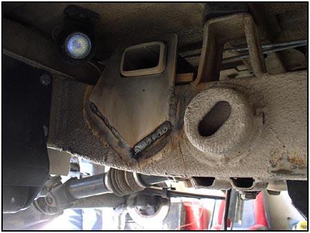
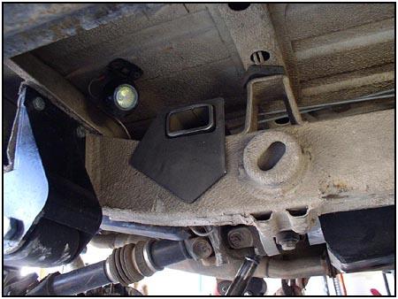
 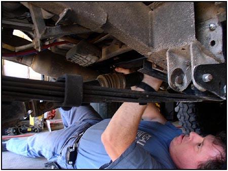 Once
everything was secured, it was time to slide the new cross member into
place. This cross member rests on top of the frame and its placement can
be adjusted to fit various axle locations. Welding it in place will be one
of the last steps. Once
everything was secured, it was time to slide the new cross member into
place. This cross member rests on top of the frame and its placement can
be adjusted to fit various axle locations. Welding it in place will be one
of the last steps. |
||
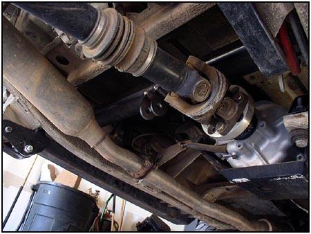  The
tabs on the cross member point down and are offset to the drivers side.
This lets the bar fall between the driveshaft and the exhaust. Rod ends (heim
joints) are attached to the bar using misalignment washers, then the bar
can twist and while the suspension articulates. The
tabs on the cross member point down and are offset to the drivers side.
This lets the bar fall between the driveshaft and the exhaust. Rod ends (heim
joints) are attached to the bar using misalignment washers, then the bar
can twist and while the suspension articulates. |
||
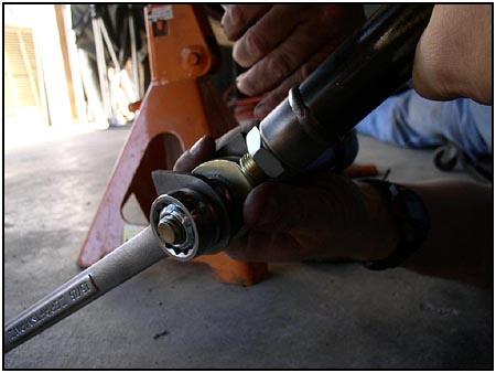
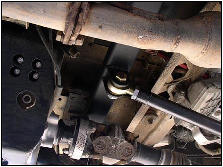
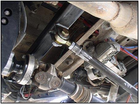 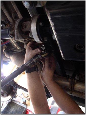 It
is best to install the rod ends half way into the bar so that there is
plenty of adjustment available in both directions. It
is best to install the rod ends half way into the bar so that there is
plenty of adjustment available in both directions.
Also, look closely at the driveshaft. You will notice an adapter that comes very close to the new cross member. Make sure there is sufficient clearance between the driveshaft and the cross member. Ours came too close for comfort, so we raised the cross member using small shims between the cross member and the frame. |
||
|
|
||
| We then assembled the axle housing end using the alternative tabs that Spidertrax supplied for attaching it to the Sidewinder housing. This is where you would use the standard brackets shown earlier to attach directly to the stock axle tube. This bar puts quite a bit of stress on the axle tube. I don't think we have to worry about that on this Spidertrax Sidewinder axle housing, but a stock housing should be strengthened with good gussets before jumping on the skinny pedal. The bracket for the stock axle has plenty of meat to grab onto (almost 180 degrees - or half way around the axle tube), but the axle housing itself could twist without additional strengthening. | ||
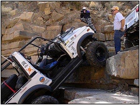
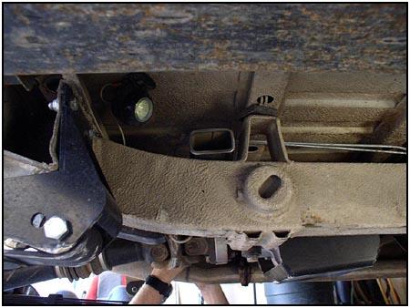  This
vehicle is a 92 Samurai, and in the newer models, Suzuki had installed
round tie-down brackets on the frame. This would be in the way if we had
to make any placement adjustments before welding. Our 'perfect' location
was closer forward than the bracket would allow. This
vehicle is a 92 Samurai, and in the newer models, Suzuki had installed
round tie-down brackets on the frame. This would be in the way if we had
to make any placement adjustments before welding. Our 'perfect' location
was closer forward than the bracket would allow. |
||
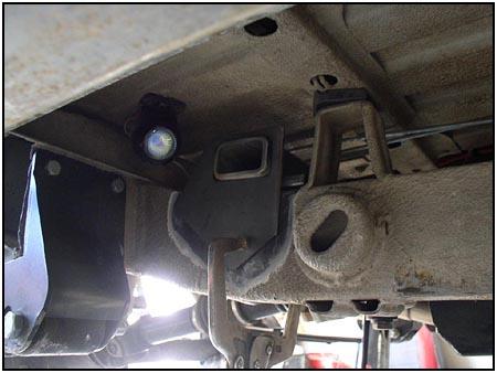
  So
a bracket adjustment was needed. Once welded in place, this bracket will
still retain all the strength of the original. So
a bracket adjustment was needed. Once welded in place, this bracket will
still retain all the strength of the original. |
||
|
|
||
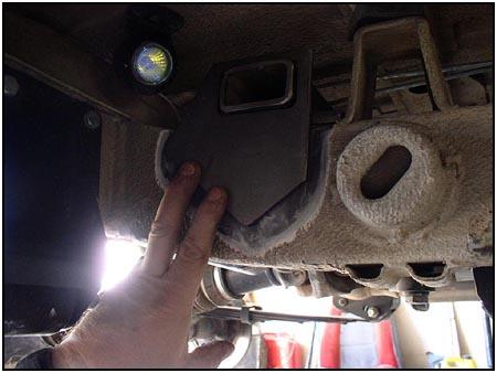
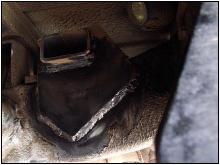
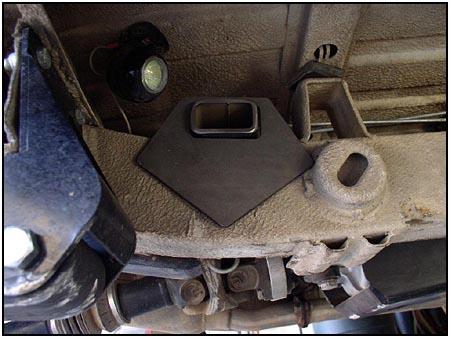
|
Here are a few shots of the adjusted side plate and how we secured it to the frame. |
||
|
|
||
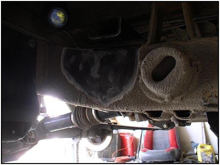
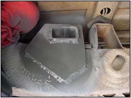  After
all welding and cleanup was done, the area was primed and then sealed
using a spray-on undercoating. The ends of the cross member can be capped
if you prefer, we just left ours open as the kit was designed. After
all welding and cleanup was done, the area was primed and then sealed
using a spray-on undercoating. The ends of the cross member can be capped
if you prefer, we just left ours open as the kit was designed. |
||
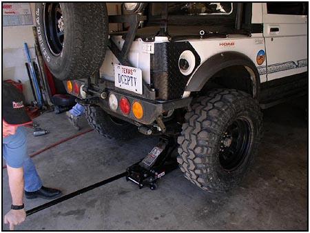
 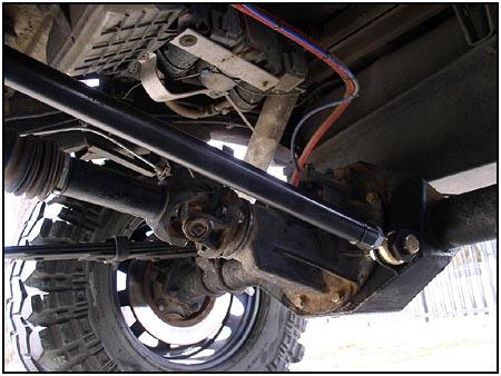 The
system is simple in design and allows for quite a bit of articulation.
Before the kit was installed, the vehicle would 'lunge' forward in a slow
rolling idle as the drive train would turn (wrapping the springs) and then
the springs would unload moving the vehicle forward. Then the process
started again. The rear of the vehicle would also squat under hard acceleration
from a stop. The kit installation resulted in a nice even
launch and an end to the 'lunge'. The
system is simple in design and allows for quite a bit of articulation.
Before the kit was installed, the vehicle would 'lunge' forward in a slow
rolling idle as the drive train would turn (wrapping the springs) and then
the springs would unload moving the vehicle forward. Then the process
started again. The rear of the vehicle would also squat under hard acceleration
from a stop. The kit installation resulted in a nice even
launch and an end to the 'lunge'. |
||
 Component
Source: Component
Source:
Spidertrax |
08/22/22 14:31:41